


 & HDD (Hard Disk Drive)?")


Let’s dive into the world of BGA (Ball Grid Array) Chip Reballing—a fancy fix for those chips that have seen better days thanks to their worn-out or damaged solder balls. Imagine these solder balls as the chip’s trusty sidekicks, bridging the gap between the chip and its circuit board, making sure those electrical connections stay golden.

But when these connections start slacking or call it quits, watch out! Your chip might start acting like a drama queen, showing signs like on-and-off behavior, sluggish performance, or even a complete meltdown. Time to roll up those sleeves and get reballing!
Imagine breathing new life into those pesky faulty BGA Chips connections, bringing them back to their prime! This approach isn’t just a wallet-saver by dodging the costly replacement of entire chips or circuit boards; it’s also a nod to the longevity of our beloved gadgets. By swapping out those worn-out solder balls, reballing ensures our devices stay on their A-game for the long haul.
And let’s not forget the green points—reballing cuts down on electronic waste. Instead of tossing out the old and ushering in the new, reballing lets us give these components a second chance at life, doing our bit to reduce electronic waste.

Why BGA Chip Needes Reballing?
Ah, the world of BGA Chips—a place where reballing isn’t just a suggestion, sometimes it’s a necessity. So, why might these chips need a little reballing TLC? Let’s dive in!
- Dry joints: The arch-nemesis of soldering. Over time, thanks to thermal cycling or just a good old dose of mechanical stress, these joints can get as brittle as a day-old cookie. And what’s the result? Dodgy electrical connections can lead to your BGA chip throwing a fit or even calling it quits.
- Overheating Concerns: Heat—the silent enemy of many BGA chips, especially those in devices that run hotter than a summer day in Death Valley. Too much heat and those solder balls start to degrade, melt, or just decide to play musical chairs. The result? A compromised chip that’s about as reliable as a cheap umbrella in a storm.
- Physical Damage Physical mishaps that can befall our beloved BGA chips—cracks, warping, delamination—you name it! Whether it’s a case of clumsy handling, too much stress, or Mother Nature having a bad day, these damages can wreak havoc on our chips. And when solder balls or connections get damaged? Electrical gremlins come out to play, causing all sorts of performance issues or even a complete chip meltdown.

Ever had your screen go black mid-game or during a binge-watching session? Talk about a cliffhanger! That sudden loss of display output is a telltale sign that your graphics chip might be crying out for some reballing love.
But wait, there’s more! Say hello to vertical or horizontal lines and those pesky dots that decide to pop up like uninvited guests on your screen. These visual hiccups aren’t just annoying; they’re flashing warning signs of deeper issues with your graphics chip or its soldered buddies.

Now, imagine hitting that power button and… nothing. Nada. Zilch. Yep, faulty solder joints under your Motherboard’s Chipset Chip can turn your device into a high-tech paperweight. With the printed circuit board (PCB) failing to make the right connections, you’re left twiddling your thumbs instead of diving into your favorite games or accessing those all-important files. Talk about a buzzkill!
Reflow Or Reballing
Reflowing chips is like the Jedi mind trick of tech repair—often magical and surprisingly effective. It’s the go-to move for fixing pesky solder joint issues without going full ‘Death Star rebuild’ with a reballing procedure. Essentially, reflowing means heating those solder joints to melting point to get them to play nice again. This can work wonders for wonky connections, spotty electrical conductivity, and those frustrating on-again-off-again chip quirks.
Why Reflowing Rocks:
- Tackling Dodgy Connections: Think of solder joints as the friendships you thought would last forever but got strained by time, stress, and too many coffee spills. Reflowing can mend those bonds, improving conductivity and reviving your chip’s performance.
- Nailing Intermittent Issues: Those sneaky microcracks and tiny defects causing your chip’s mood swings? Reflowing can spot and fix them, reshaping the solder into strong, stable connections and giving your chip a more balanced personality.
- Easy-Peasy Repair: Reflowing is like the DIY home improvement of chip repair—less mess, less fuss, and no need for a toolbox that looks like it belongs in a sci-fi movie. A heat gun, hot air rework station, or even your oven can do the trick, making it a budget-friendly and accessible fix for common solder joint woes.
The Reflowing Reality Check:
- Not a Cure-All: While reflowing works wonders for many solder-related snags, it’s not the answer to every chip conundrum. Major defects or internal issues might need the big guns—like reballing or even a complete chip makeover—to get things back on track.
Suggested Articles:
- What Is Reflow? – Explaining Reflowing With Types & Procedure
- How To Reflow GPU Or Chipset Chip Of Desktop’s Motherboard?
- How To Repair A Broken Graphics Card By Reflow?
- Fixing Laptop’s Display Problem By Reflowing Its GPU (Graphics Chip)
Cost Of Reballing A BGA Chip
The cost of BGA chip reballing—the elusive variable expense that keeps us all guessing! So, what’s cooking in the cost cauldron? Let’s break it down.
- Chip & Reballing Components: First up, the star of the show—the replacement BGA IC (Integrated Circuit) Chip (if required). Prices of a new chip can range from a modest 10$ to a jaw-dropping 200$. And don’t forget about the Fixed Rate Reballing Service Fee, that’s the service provider’s wildcard, with prices that can dance around 30$ to 100$.
- Complexity of the Reballing Process: Complexity—the spice of life in the reballing world! The number of solder joints needing a makeover, the type of solder playing the lead role, and the fancy equipment needed to pull it all off—these are the ingredients that can send the cost soaring faster than a SpaceX rocket.
- Type of Equipment and Services Required: Not all reballing setups are created equal. High-quality equipment and top-notch services can fetch a premium price tag. Think of it as paying for the VIP experience—a guarantee of precision and reliability that’s worth its weight in gold.
- Geographical Location and Service Provider: Location, location, location! Whether you’re in the bustling tech hubs of the United States or Europe or enjoying the cost-friendly services of India, geography plays a starring role in the reballing cost saga. Lower labor and operational costs in certain regions can lead to more wallet-friendly prices, while others might require a bit more budget flexibility.
List Of Necessary Supplies Needed For Reballing
Reballing—the delicate dance of reviving our beloved BGA chips! But like any dance, you need the right gear to make sure you don’t step on any toes—or in this case, solder balls. So, what’s in the toolkit for a successful reballing extravaganza? Let’s dive in!
#1: BGA Reballing Stencil
The BGA reballing stencil—a humble piece of metal that’s the unsung hero of the reballing world! Crafted with the precision of a Swiss watchmaker and the durability of a superhero’s shield, this little marvel is more than just a pretty face.
Imagine a thin, flat piece of metal, often stainless steel, that’s been meticulously crafted to include cutouts or openings. These aren’t just any cutouts—they’re designed to mirror the arrangement and size of the solder balls on a specific BGA chip model. Think of it as a custom-tailored suit for your BGA chip, ensuring a perfect fit every time!
Now, you might ask, why all the fuss about a stencil? Well, my friend, the use of a BGA reballing stencil is the secret sauce for achieving consistent, reliable results in the reballing arena. It’s the safety net that catches those potential errors and the roadmap that eliminates guesswork. By ensuring solder balls are evenly distributed, properly aligned, and securely attached, the stencil keeps those electrical connections humming and the BGA chip functioning like a champ post-reballing.
#2: Solder Balls
Solder balls—the tiny, often overlooked gems that play a crucial role in the reballing dance! Whether they’re classic blends of tin and lead or the lead-free hipsters like SnAgCu or SnAgCuBi, these small spheres are the unsung heroes bridging the gap between our BGA chips and circuit boards. But why should we care about it? Let’s dig in!

- Material Composition: Ah, the blend! Whether you’re team traditional with tin and lead or riding the wave of lead-free alloys, the material composition of solder balls is your ticket to reliable and durable connections. It’s like choosing the right wine for dinner—pick the wrong one, and you’re in for a sour experience. High-quality solder balls are the connoisseurs of the bunch, crafted to industry standards, ensuring a consistent performance that’s as reliable as your morning coffee.
- Size and Compatibility: Size matters—especially in the world of solder balls! Selecting the perfect size is like finding the right pair of shoes; too big, and you’re tripping over yourself, too small, and you’re squeezing into discomfort. The wrong size can lead to a messy reballing process, poor connections, or even a chip and board face-off that ends in damage. So, it’s crucial to pick solder balls that are just the right fit for your BGA chip, ensuring a seamless reballing performance.

#3: Flux
Let’s talk flux—the behind-the-scenes superstar in the soldering and reballing world! This chemical maestro comes in liquid, paste, or gel form, rolling up its sleeves (or should we say caps?) to prep our electronic components, such as BGA chips and solder balls, for the soldering stage. But what makes flux the go-to sidekick for soldering aficionados? Let’s unravel its secrets!
- Oxidation and Contaminant Removal: Metal surfaces can get a little rusty over time, and not just in the literal sense. Oxidation and contaminants can sneak in, throwing a wrench in our soldering plans and weakening those precious solder joints. Enter flux—the cleaning superhero that swoops in to dissolve and banish these unwanted guests, leaving behind pristine surfaces ready for soldering action.
- Solder Wetting: Picture a molten solder flowing smoothly, spreading evenly like a dream on a pillow—this is solder wetting, and flux is the backstage director making it all happen. By reducing the surface tension of the solder, flux ensures it glides across the surfaces with grace, forming strong, reliable bonds that even a superhero would envy.
- Enhanced Adhesion: Clean surfaces and smooth solder wetting—what’s the result? Strong and durable solder joints that stand the test of time! Flux plays matchmaker, bringing the BGA chip and solder balls together in a loving embrace that boosts reliability and longevity, making the reballing process a true masterpiece.
Types of Flux:
- Rosin Flux: Meet rosin flux—the classic choice made from natural rosin or its synthetic counterparts. With its stellar cleaning and wetting properties, it’s the go-to for electronics soldering, delivering performance that’s as reliable as your morning coffee routine.
- Water-Soluble Flux: Easy cleanup, anyone? Water-soluble fluxes are the clean freaks of the bunch, designed to wash away with water post-soldering. Perfect for those who like their soldering process with a side of cleanliness.
- No-Clean Flux: Why clean when you don’t have to? No-clean fluxes are the low-maintenance pals that leave little to no residue behind, saving you from the post-soldering cleanup hassle. It’s like having your cake and eating it too!

#4: Cleaning Solvents
Cleaning solvents—these liquid wonders are specially formulated to tackle dirt, grease, oils, flux residues, and other pesky contaminants, all without causing harm or leaving behind any nasty residues. But why should we care about these cleaning champs? Let’s dive into the world of cleaning solvents and uncover their magic!
- Contaminant Removal: Picture you’ve just finished soldering those BGA chips, and now it’s time to clean up the mess. Enter cleaning solvents—the cleanup crew that swoops in to banish flux residues, oxidation, and other contaminants that could sabotage your solder joints. With their superhero powers, cleaning solvents leave surfaces squeaky clean and ready for action!
- Surface Preparation: Smooth surfaces are the name of the game, whether you’re soldering, bonding, painting, or embarking on any surface-sensitive mission. Cleaning solvents play the role of the ultimate prep team, ensuring surfaces are clean, smooth, and primed for whatever comes next. It’s like giving your project a VIP spa treatment, ensuring optimal performance and adherence every time!
- Compatibility: Versatility is the middle name of cleaning solvents! From metals and plastics to ceramics and electronic components, these liquid wonders play nice with a wide range of materials. Whether you’re in electronics manufacturing, automotive, aerospace, or beyond, cleaning solvents have got you covered, making them the go-to choice for all your cleaning adventures.

#5: Rework Station or Hot Air Gun
Rework stations and hot air guns—a tech wizard’s best friend when it comes to electronics repair and reballing. Picture you’ve got a stubborn BGA chip or some solder balls that need a touch of heat to play nice. That’s where these tools come in, spitting out a stream of hot air with temperatures you can tweak to your heart’s content. This lets you warm up those components just right, melting solder joints like a pro without frying any sensitive parts.
Functions and Perks of a Rework Station or Hot Air Gun:
- Controlled Heating: First off, these babies are all about the heat—controlled heat, to be precise. They let you dial in the perfect temperature for your BGA chips and solder balls during the reflow soldering dance. You can hit that sweet spot where the solder melts just right, without turning your chip into a crispy critter or messing up nearby components.
- Solder Melting and Reflow: With a blast of hot air aimed at your BGA chip and solder balls, these tools get down to business, melting the solder and making reflow happen. This action helps those solder balls make sturdy connections with the BGA chip’s pads or contact points, setting the stage for top-notch electrical and mechanical performance.
- Precision and Accuracy: Last but not least, these tools are all about hitting the mark with precision and accuracy. Being able to fine-tune the temperature and airflow is crucial for tasks like reballing and soldering. It’s the key to getting consistent, high-quality results, while keeping the risk of component damage to a minimum.
If you’re in the market for the crème de la crème of BGA reworking machines, be prepared to shell out upwards of $10,000. What do you get for that kind of cash? Think advanced features, precision controls that would make a Swiss watch jealous, and automation that practically does the job for you. It’s the Rolls-Royce of reworking machines, offering unmatched precision, durability, and reliability for those intricate rework and repair tasks.
But maybe you don’t need all the fancy extras. If you’re looking for something more basic, you can snag a BGA reworking machine for around $2,000. Sure, it won’t have all the bells and whistles, but it’ll get the job done for your everyday rework and soldering needs without breaking the bank.
So, which one should you go for? Well, it all boils down to your specific requirements, budget, and what you’ll be using the machine for. Whether you’re a business or an individual, there’s a BGA reworking machine out there that’s just right for you.
Now, Let’s Move On To The Reballing Procedure
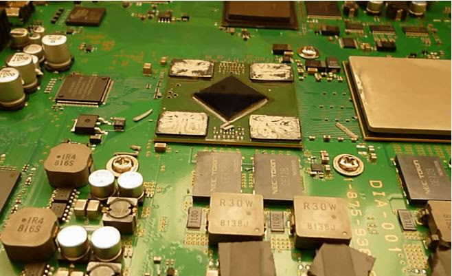
Alright, tech enthusiasts, today we’re diving deep into the intricate art of reballing the PlayStation 3 Video Graphic BGA (Ball Grid Array) Chip. Buckle up, because this is some next-level stuff. And hey, even if you’re not messing with a PS3, the skills you pick up here will come in handy for reballing other BGA chips down the line.
Now, let’s get one thing straight: reballing isn’t for the faint of heart. It’s a meticulous, time-consuming dance of removing old solder balls, giving everything a good clean, and then delicately placing new solder balls for those all-important electrical connections. Mess up a step, and you could end up with a chip that’s more doorstop than high-tech marvel.
If you’re a reballing newbie or your experience with BGA chips is, let’s say, limited, do yourself a favor and consult with a pro. An experienced engineer or technician can offer invaluable advice, guide you through the process, and make sure you don’t accidentally turn your precious chip into a paperweight.
Step #1: Disassemble The Console
So, let’s kick off this reballing adventure by getting up close and personal with your gaming system or console. We’re going to roll up our sleeves and dive into disassembling the beast to get to that PlayStation 3 Video Graphic BGA Chip that’s begging for a makeover.
Here’s your game plan:
- Preparation: First things first, let’s get organized. Clear off a clean workspace – trust me, you don’t want to lose any screws in a sea of clutter. Grab your trusty screwdrivers, spudgers, tweezers, and any other tools you’ll need to make this disassembly a breeze.
- Referencing a Tutorial: If the thought of taking apart your prized console sends shivers down your spine, fear not! There are plenty of helpful souls out there who’ve posted disassembly tutorials on platforms like YouTube. Watch a video or two to get a feel for the process and arm yourself with some visual guidance.
- Follow the Steps: Now that you’re prepped and have a rough idea of what’s ahead, it’s time to get down to business. Start by removing any external screws and panels to reveal the console’s inner workings. Take it slow and steady, treating each step like a delicate operation – because, well, it is.
- Locate the Motherboard: Once you’ve cracked the outer shell, you’ll find yourself face to face with the motherboard. It’s usually tucked away and secured with more screws and connectors. Carefully remove these to free the motherboard from its case, but remember: gentle hands only!

Step #2: Remove The Heat Sink
If you’ve successfully liberated that motherboard from its console cage. Now, it’s time to get up close and personal with the heat sink cover that’s been keeping our Graphic Chip cool and cozy.
- Preparation: First off, let’s set the stage for success. Lay that motherboard down on a flat, stable surface – we’re talking no wobbling allowed. Grab yourself a skinny knife or a similar tool to help you with this delicate operation.
- Careful Removal with a Knife: Now, this part requires a gentle touch. Slide that skinny knife between the heat sink cover and the motherboard, gently working your way around the edges. Apply just enough pressure to loosen the cover from any adhesive or thermal paste without going full samurai on your motherboard. Take your time, be patient, and keep those scratch-happy hands steady.
- Using a Heat Gun (Optional): If you find yourself wrestling with that stubborn heat sink cover, it might be time to bring in the big guns – literally. Grab a heat gun and give the heat sink a little warm-up session. This should soften up any adhesive or thermal paste, making it easier to slide that knife through. Once warmed, give the knife another go, prying and lifting the cover with newfound ease. Just remember, heat is your friend here; it’ll make the removal process smoother and significantly reduce your chances of inflicting accidental chip or motherboard damage.
- Handle with Care: Last but not least, safety first! The heat sink cover might look harmless, but those edges can be surprisingly sharp. Hold it securely to avoid any slip-ups that could lead to unwanted injuries. And once you’ve successfully removed the cover, tuck it away in a safe spot – we don’t want any disappearing acts or accidental damage ruining our reballing party.

Step #3: Clean the GPU Chip
You’ve got that heat sink cover off, and now it’s time to get down and dirty with some cleaning action. We want that Graphic Chip’s surface to be as pristine as a freshly waxed sports car before we dive into the reballing fun.
- Gather Supplies: First things first, let’s assemble our cleaning arsenal. Grab yourself some 90% pure isopropyl alcohol – none of that watered-down stuff – and a cotton ball or lint-free cloth. We want to make sure we’re using high-purity isopropyl alcohol to tackle any stubborn residues like a pro.
- Dip and Wipe: Now that you’re locked and loaded, dip that cotton ball or cloth into the isopropyl alcohol. You want it to be moist but not dripping wet – we’re cleaning a chip, not giving it a bath! Gently wipe down the Graphic Chip’s surface, applying light pressure to banish any thermal paste, dust, or debris. Think of it as giving the chip a spa day – thorough but oh-so-gentle.
- Inspect and Dry: Once you’ve scrubbed away all the nasties, give your Graphic Chip a once-over to make sure it’s sparkling clean. Let it air dry for a few minutes, or if you’re feeling fancy, grab a can of compressed air to blow away any lingering moisture or lint. Make sure that chip is bone-dry before you move on to reballing – we want those new solder balls to stick like glue!
Step #4: Put Liquid Flux
You’ve cleaned up that Graphic Chip like it’s ready for a red-carpet event. Now, let’s get it prepped and primed for some reballing action with our trusty liquid flux.
- Select the Right Flux: First things first, you’ll want to pick a high-quality liquid flux that’s tailor-made for electronics soldering and rework. Check the label to make sure it plays nice with the materials and components of your Graphic Chip – we don’t want any surprise chemistry experiments happening on our watch.
- Apply Flux to Corners: Armed with your precision applicator or a tiny brush, it’s time to get artsy. Apply a modest amount of flux to each corner of the Graphic Chip, focusing on where those pesky solder balls like to hang out. The goal here is even distribution, so take your time and aim for perfection.
- Avoid Excessive Application: Now, a word of caution – less is definitely more when it comes to flux. Resist the urge to go overboard, as too much flux can turn your reballing adventure into a sticky mess. A thin, even layer is all you need to get those solder balls ready for their big debut.

Step #5: Put Liquid Flux
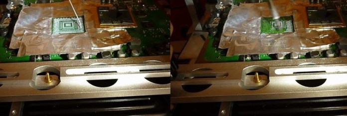
You’ve prepped our Graphic Chip with liquid flux, and now it’s time to play defense and protect those surrounding motherboard components. We don’t want any heat damage or rogue solder splatter crashing our reballing party.
- Crafting a Protective Cover with Foil Paper: Here’s where a little DIY ingenuity comes into play. Grab some foil paper – you know, the stuff you use to wrap up leftovers – and let’s fashion ourselves a protective shield.
- Measure and Cut: First up, measure out a piece of foil paper that’s large enough to cover the area around the Graphic Chip. You want to create a barrier that shields the nearby components from any stray heat or solder action.
- Shape and Secure: Carefully mold the foil paper around the Graphic Chip and surrounding components, making sure to create a snug fit that covers all the vulnerable areas. You can use tape or a gentle adhesive to secure the foil paper in place, ensuring it stays put during the reballing process.

Step #6: Put Heat Sensor
Now, we’re pulling out all the stops to make sure this reballing process goes off without a hitch! You’ve prepped our Graphic Chip, shielded the motherboard’s surrounding components with our DIY foil paper cover, and now it’s time to bring in some high-tech backup with a heat sensor wire.
- Attaching a Heat Sensor Wire: This nifty little wire is going to be our eyes and ears during the reballing process, helping us keep a close eye on temperatures and ensuring our Graphic Chip stays cool as a cucumber.
- Positioning the Heat Sensor Wire: Carefully place the heat sensor wire on a side corner of the Graphic Chip, making sure it’s securely attached and won’t budge during the reballing action. You want the sensor to have direct contact with the chip’s surface to accurately measure temperatures.
- Securing the Sensor: Once the heat sensor wire is in place, use a gentle adhesive or tape to secure it to the Graphic Chip. Make sure it’s snug but not too tight – we don’t want to apply any unnecessary pressure that could interfere with the sensor’s readings.
- Testing the Sensor: Before diving into the reballing process, give the heat sensor wire a quick test to make sure it’s working properly. You want to confirm that it’s providing accurate temperature readings and that it’s ready to keep a vigilant watch over our Graphic Chip.

Step #7: Put Motherboard On The BGA Rework Machine
We’ve prepped our Graphic Chip, shielded the surrounding motherboard components, attached our trusty heat sensor wire, and now it’s time to bring it all together on the BGA Rework Machine. This bad boy is our ticket to reballing glory, providing us with the precision and control we need to nail this reballing process.
- Position the Motherboard: Let’s start by placing our motherboard onto the BGA Rework Machine’s platform or tray. Take a deep breath, steady those hands, and carefully center and align the motherboard with the machine’s heating and soldering elements. Precision is the name of the game here, so take your time to get it just right.
- Tighten the Holding Panels: With the motherboard in place, it’s time to lock it down. Use the adjustable holding panels or clamps that come with the machine to secure the motherboard. Gently tighten these around the edges of the motherboard to ensure it’s held securely and won’t budge during the reballing process.
- Inspect the Protective Cover and Heat Sensor Wire: Before we fire up the machine, give your protective foil paper cover and heat sensor wire one last look. Make sure they’re intact, properly positioned, and won’t interfere with the machine’s heating and soldering elements. Make any tweaks or adjustments needed to ensure they’re ready to do their jobs effectively.

Step #8: Removing The Old GPU Chip
Alright, team, it’s showtime! We’ve got our motherboard snugly positioned on the BGA Rework Machine, and now it’s time to apply some controlled heat to our Graphic Chip to get those solder balls nice and melty for removal. This is where the rubber meets the road, so let’s get down to business!
- Position the Heater: First up, carefully position the heater element or nozzle of your BGA Rework Machine over the Graphic Chip. Make sure it’s covering the entire chip’s surface and aligns perfectly with our protective foil paper cover and heat sensor wire. This heater is our MVP, providing the heat we need to melt those solder balls during the desoldering process.
- Set the Initial Temperature: Let’s kick things off by setting the machine temperature to a medium setting, around 150 degrees Celsius. Give the chip about 1 minute to preheat at this temperature. This gradual warm-up helps ease the chip and surrounding components into the heat, reducing any thermal shock or stress.
- Increase the Temperature: After our 1-minute preheat session, crank up the machine temperature to 250 degrees Celsius. Maintain this higher temperature for an additional 2 minutes to keep melting those solder balls and get them ready for removal. Keep a close eye on the temperature using your heat sensor wire and monitoring device to make sure we’re heating things up just right.
- Check for Solder Melting: As we hit and maintain that 250 degrees Celsius mark, keep a sharp lookout for any changes in the solder’s appearance or texture. You’re looking for signs that those solder balls are melting – think of it as a mini chemistry lesson in action! If needed, tweak the heat settings a smidge to ensure all the solder balls are good and melted.
- Remove the Chip with Chip Holder: Once you’re confident the solder has melted enough, it’s time for the grand finale – removing the chip from the BGA Rework Machine. Grab a chip holder or tweezers, and gently but securely lift that chip out of its cozy heating chamber. Place it on a heat-resistant surface or holder to cool down before we dive into the reballing fun.

Step #9: Clean The Circuit On The Motherboard
e’ve safely removed our Graphic Chip from the motherboard using the BGA Rework Machine, and now it’s time to roll up our sleeves and get that Printed Circuit Board (PCB) spick and span for reballing. We want this PCB surface to be cleaner than your grandma’s kitchen floor!
- Apply Soldering Flux: Let’s kick things off by applying a dab of soldering flux to the BGA circuit surface on the PCB. This magical elixir helps activate and lift any lingering solder residues, contaminants, or oxidation, giving us a clean canvas for the reballing masterpiece we’re about to create.
- Remove Remaining Solder with Soldering Iron: Armed with our trusty soldering iron with a fine tip, let’s carefully heat and remove any remaining solder from the PCB surface. Gently guide the soldering iron over the flux-coated areas, melting away any residual solder like a hot knife through butter. Make sure your soldering iron is clean and up to temperature to ensure a smooth and effective solder-removing operation.
- Cut and Place Desoldering Wire: Now, let’s introduce our secret weapon – desoldering wire. Cut a piece to the appropriate length and lay it on the flux-coated BGA circuit surface of the PCB. This wonder wire is designed to absorb and soak up melted solder, contaminants, and flux, leaving our PCB surface as clean as a whistle.

- Inspect and Clean: Once you’ve worked your cleaning magic, give the PCB surface a thorough once-over. Make sure all solder, flux, and contaminants have been banished to the scrap heap. If needed, repeat the cleaning process or use a clean brush, cloth, or a blast of compressed air to ensure every nook and cranny is free of debris, giving us a flawless surface for reballing.
Step #10: Clean The Chip
We’ve got our PCB all cleaned up and ready to go, and now it’s time to turn our attention to the star of the show – our freshly removed Graphic Chip. We want this bad boy to be as clean as a whistle for the reballing process, so let’s dive right in!
- Attach the Chip to Chip Holder: First up, let’s get our Graphic Chip strapped in and ready for action. Securely attach the chip to a chip holder or specialized fixture designed to keep it stable during the cleaning and reballing process. Make sure the chip is sitting pretty and level on the holder to ensure effective cleaning without any potential mishaps.
- Apply Soldering Flux to the Chip: With our Graphic Chip securely in place, it’s time to break out the soldering flux once again. Apply a smidge of flux to the chip’s surface – this stuff is our secret weapon for activating and lifting any lingering solder residues, contaminants, or oxidation, leaving our chip squeaky clean and ready for reballing.
- Wave Soldering Iron Over the Chip: Grab your trusty soldering iron with a fine tip and let’s get to work. Carefully guide the iron over the flux-coated surface of the Graphic Chip, letting the heat melt away any remaining solder and activate the flux. Make sure your soldering iron is clean and up to temperature to ensure a smooth and effective cleaning operation without causing any damage to our precious chip.
- Place Desoldering Wire on the Chip: Now, let’s bring in our cleanup crew – desoldering wire. Cut a piece to the right length and lay it gently on the flux-coated surface of the Graphic Chip. With everything in place, guide your soldering iron over the wire, melting the solder and letting the desoldering wire do its thing, soaking up all that molten mess and leaving our chip looking like new.

Step #11: Apply Flux On The Chip
We’ve got our Graphic Chip cleaned, and now it’s time to lay down some solder flux. This step is absolutely crucial for making sure our new solder balls stick just right and play nicely with our chip.
- Select the Solder Flux: First up, let’s pick the perfect solder flux (non-liquid) for our mission. Opt for a high-quality flux tailored for reballing and electronics soldering. Make sure it’s a good match for our Graphic Chip’s materials to ensure smooth sailing and stellar results.
- Apply Solder Flux to the Chip: Time to get hands-on again! Scoop up a small amount of solder flux onto your finger or a specialized applicator tool. Carefully spread and apply the flux to the Graphic Chip’s surface, aiming for even coverage and distribution. Remember, a little goes a long way, so keep it controlled to avoid any potential mishaps.
- Ensure Even and Thin Coverage: As you apply the solder flux, keep a sharp eye on achieving that thin, even layer we’re aiming for. Think of it like painting a masterpiece – precision and consistency are key! Focus on the chip’s corners and edges to ensure thorough coverage and strong adherence of the flux.

Step #12: Install The BGA Reballing Stencil
We’ve got our Graphic Chip prepped with solder paste and flux, and now it’s time to bring in the reballing stencil to help us nail that perfect solder ball placement. Let’s dive in!
- Select the Reballing Stencil: First off, let’s pick the right reballing stencil for our Graphic Chip and the specific reballing process we’re tackling. Ensure the stencil is clean, free from any gunk or residues, and in tip-top shape for delivering accurate and precise results. A well-maintained stencil is key to achieving flawless solder ball placement.
- Position the Reballing Stencil: With our chosen stencil in hand, it’s time to get it lined up over our Graphic Chip. Carefully place the middle and upper sections of the stencil over the chip’s surface, ensuring the alignment holes or guides on the stencil match up perfectly with the corresponding markers or features on the chip and motherboard. Take your time here – precision is crucial for a successful reballing process.
- Secure the Reballing Stencil with Screws: Once the stencil is perfectly positioned, let’s lock it in place. Use the provided screws or clamps to secure the stencil firmly over the Graphic Chip. Tighten those screws evenly and snugly to ensure the stencil stays put and doesn’t budge during the reballing process. Keep an eye on keeping the stencil flat and level over the chip’s surface to ensure those solder balls land exactly where they should.

Step #13: Put Balls On The Stencil
Alright, team, we’re at the heart-pounding moment of our reballing journey – it’s time to bring on the solder balls! Let’s dive into the action-packed steps of applying these solder balls like a pro!
- Prepare the Solder Balls: First up, make sure you’ve got the right solder balls for the job. Check that they’re the correct size and type compatible with your Graphic Chip and reballing stencil. With solder balls coming in various sizes and compositions, picking the right ones is key to nailing this step without a hitch.
- Place Solder Balls on the Metal Sheet: Grab your trusty metal sheet or tray and get those solder balls lined up. Carefully distribute them evenly across the metal surface, making sure they’re not sticking together or clumping. Use a pair of tweezers or a specialized tool to handle and place these little guys with precision and accuracy.

- Position the Metal Sheet Over the Reballing Stencil: With your solder balls ready to roll, it’s time to position them over our Graphic Chip. Carefully place the metal sheet, loaded with solder balls, over the reballing stencil covering the chip. Ensure the solder balls align perfectly with the holes and openings in the stencil, ready to drop into place on the chip’s surface.
- Shake the Chip Holder Gently: Now, let’s get those solder balls settling into their new home on the chip. Gently shake or tap the chip holder or metal sheet to help the solder balls fall into the holes and gaps on the chip’s surface. This gentle motion will aid in distributing and aligning the solder balls, ensuring they snugly fill the gaps and holes on the chip.
- Inspect and Adjust if Necessary: With the solder balls in place, take a moment to inspect the chip. Ensure all the holes and gaps are filled with solder balls and there are no missing or misaligned ones. If you spot any gaps or misalignments, make the necessary adjustments to ensure every spot on the chip is covered with these crucial solder balls. Remember, a thorough inspection now can save you from potential issues down the road.

Step #14: Remove The Stencil Upper Cover
With our solder balls perfectly placed and aligned on the chip, it’s crucial to proceed with the utmost care and precision in this step. Slowly and gently remove the upper holder part from the chip stand, ensuring no sudden movements or disturbances that could displace our hard-earned solder balls. Keep your movements smooth and steady to maintain the integrity of the solder ball placements on the chip’s surface.
Once the upper holder part is safely removed, take a moment to inspect the solder balls on the chip. Ensure they remain in their designated spots, properly aligned and distributed across the chip’s surface. If you notice any misplaced or misaligned solder balls, make the necessary adjustments with a pair of tweezers or a specialized tool to gently reposition them back into place.

Step #15: Solder Balls Using Heat Gun
Now, let’s bring the heat—literally! We’ll reflow these solder balls onto the Graphic Chip using our trusty heat gun. Here’s how we’ll execute this step with finesse and precision:
- Prepare the Heat Gun: Let’s double-check our heat gun. It should be clean, in tip-top shape, and set to a gentle, low temperature and air pressure suitable for reflow soldering. We want to avoid blasting our solder balls off the chip, so low and slow is the way to go! Adjust those settings to their lowest, ensuring we have gentle and controlled heating during the reflow process.
- Position the Heat Gun: With our heat gun in hand, let’s carefully position the nozzle or tip at an appropriate distance above the Graphic Chip. Aim for even and consistent heat coverage across the chip’s surface. We’ll maintain a steady hand and constant distance and angle to ensure uniform heating. Remember, we want to avoid overheating or creating any hotspots that could potentially damage our chip or solder balls.
- Reflow the Solder Balls: Apply gentle and controlled heat to reflow our solder balls. We’ll keep a close eye on the reflow process, making any necessary adjustments to our heat gun’s settings or position to ensure everything is going smoothly and our solder balls are melting and bonding as they should.
- Inspect the Reflowed Solder Balls: With our reflow process complete, it’s time for a thorough inspection. We’ll carefully check the Graphic Chip and solder balls to ensure they’ve melted, wetted, and bonded properly to the chip’s pads and connections. We’ll be on the lookout for any signs of incomplete melting, solder bridging, or misalignment and make any necessary adjustments or corrections to ensure optimal soldering quality and reliability.
- Cool Down and Clean the Chip: After our reflow dance, let’s allow our reflowed solder balls and Graphic Chip to cool down naturally to room temperature. Once cooled, we’ll give the chip a careful clean to remove any flux residues or contaminants using a suitable cleaning solution, brush, or cloth. This final touch ensures a clean and reliable solder joint and connection, setting the stage for our Graphic Chip’s grand return to its prime performance!

Step #16: Apply The Flux On GPU’s Circuit
Now, it’s time to bring our chip back home—onto its designated spot on the motherboard or circuit board. Let’s dive into the next crucial steps of our reballing journey:
- Apply Liquid Solder Flux: We’ll start by carefully applying a few drops of our trusty liquid solder flux onto the reflowed solder balls and circuit of our Graphic Chip. This step ensures that we facilitate proper wetting, bonding, and reflow during the repositioning and alignment process.
- Spread the Flux Gently: With our liquid solder flux applied, let’s gently spread and distribute it evenly across the surface of the reflowed solder balls and circuit of our Graphic Chip. Whether we use our finger or a clean applicator tool, our goal is uniform coverage across all areas to ensure optimal wetting and bonding during the repositioning and alignment process.
- Reposition the Chip: With our chip prepped and ready, let’s carefully pick it up and reposition it back onto its designated spot on the motherboard or circuit board. We’ll align the chip meticulously with the corresponding pads, connections, and guiding marks on the board, ensuring perfect placement and orientation.
- Match the Guiding Mark: Ah, the guiding mark! This little indicator on our motherboard or circuit board is our best friend right now. We’ll locate it and align our chip’s orientation and position carefully with this guiding mark. Taking our time to match the mark ensures accurate and correct placement, preventing any potential misalignment or incorrect placement of the chip.

Step #17: Reflow The Chip
After meticulously repositioning our Graphic Chip and aligning it perfectly with the guiding mark on the motherboard or circuit board, it’s time to perform the reflow soldering. This step ensures that our solder joints bond seamlessly, creating a robust connection between the chip and the board.
Let’s get into the nitty-gritty of reflowing our Graphic Chip:
- Prepare the Heat Source: Our BGA Rework Machine needs to be in top-notch condition. We’ll set the heat temperature to around 250°C (482°F) and keep the air pressure on a low setting to ensure the solder balls stay put.
- Position the Heat Source: Now, let’s carefully position our reflow oven heating elements above the Graphic Chip and motherboard or circuit board. We want to maintain a steady distance, angle, and heating profile to ensure uniform heating and prevent any potential damage.
- Reflow the Graphic Chip: This is where precision meets performance. Here’s our temperature and timing profile for the reflow process:
- Preheat Stage: We’ll start by gradually raising the temperature to 150°C (302°F) and maintain it for 1 minute. This preheating stage prepares the chip and components for the reflow process.
- Soak Stage: Next, we’ll ramp up the temperature to 250°C (482°F) and maintain it for 2 minutes. This allows the solder to melt, wet, and bond properly between the chip and the board’s pads and connections.
- Cool Down Stage: Finally, we’ll gradually reduce the temperature to room temperature over 3-5 minutes. This gives the solder joints time to solidify, ensuring a strong bond.
- Monitor the Reflow Process: Throughout the reflow process, we’ll keep a close eye on the appearance, behavior, and flow of the solder. We’re looking for proper melting, wetting, and bonding of the solder joints. If we spot any issues like incomplete melting, bridging, or voids, we’ll make the necessary adjustments to ensure optimal soldering quality and reliability.
- Cool Down and Inspect the Solder Joints: Once the reflow process is complete, we’ll let our reflowed solder joints, Graphic Chip, and motherboard or circuit board cool down naturally to room temperature. After cooling, we’ll inspect the solder joints and connections for uniformity, consistency, and quality, ensuring optimal reflow results and the functionality of our repaired device.

Step #18: Assemble Back Everything
We’ve made it through the reballing process, and now it’s time to bring everything back together and put our device to the test. Let’s dive into the final steps:
Reattach the Chip’s Heat Sink:
- Carefully position and align the chip’s heat sink over the Graphic Chip on the motherboard or circuit board.
- Ensure the heat sink aligns perfectly with the mounting holes and thermal pads or paste on the chip.
- Gently press down on the heat sink to secure it in place.
- Reattach any screws, clamps, or brackets to firmly hold the heat sink to the motherboard or circuit board.
Assemble the Hardware Components:
- Once the heat sink is secured, let’s carefully reassemble the remaining hardware components, connectors, cables, and screws.
- Ensure all components are aligned, seated, and secured properly to avoid any loose connections, misalignments, or mechanical issues that could affect the device’s functionality or performance.
Test the Device:
- With our device fully assembled, let’s power it on and perform a series of functional tests, diagnostics, or operational checks.
- Monitor the device’s behavior, display, audio, connectivity, and other essential functions to ensure it operates correctly.
Functional Test:
- Check all the device’s features, functions, and operations to ensure they work correctly and respond as expected.
- Test the device under various conditions, scenarios, or usage patterns to identify any potential issues or malfunctions.
Alright, tech aficionados, if your gadget’s humming along without a hitch, give yourself a virtual high-five! But, if it’s throwing a temper tantrum instead of playing nice, let’s dig into why that might be. Maybe you hit a snag during an update or installation. Or perhaps, sadly, your trusty chip has kicked the bucket and needs a replacement. Time to roll up those sleeves and tackle this systematically to pinpoint the glitch and whip that device back into tip-top shape.
It’s been a journey of precision, skill, and teamwork! Whether our device powers up flawlessly or needs a bit more attention, we’ve learned valuable lessons along the way. Let’s celebrate our accomplishments, learn from any challenges, and continue to refine our reballing skills for future projects. Great job, everyone!


Hi Madhur! Excellent blog you have shared. I don’t think there is any other simple way to understand reballing. You have beautifully discussed BGA chip reballing and its requirements. I am also working in the same field for the last 20 years and therefore know very well about the subject(Reballing). Good Luck for this one.
Really a great content you have shared here for BGA Reballing!
omg …my new fav place to visit…. http://www.deskdecode.com 🙂
Now that’s a very smart procedure for this precise task!
Congratulations for your perfect site. Your instructions are always very detailed and make our lives easier 🙂
I have a question about this procedure. Humm….more specific.. a question before starting the procedure. Nowadays, most of the motherboards we meet, has 2 chips for the GPU. The nvidia chip and the IC chip . We can follow the procedure at both of these chips, right ? Both of these have solder balls. I am wondering if you have a solution to locate firstly, which of the chip has the problem and we have no image in the screen or lines or… etc. If we have no solution about this, we have to follow the reballing procedure for the pair of GPU’s chipsets, right ?
First, try to reball the main Graphics Chip (like Nvidia or AMD), because most of the times it’s the only one who used the most and gets faulty.
Thanks for sharing this wonderful and informative content with all of us. Keep it up.
Hi, i liked your blog.
I have a amd chip that needs reballing. I was asked to spend 2500 rs for reballing.
still my laptop is working on the single intel onboard graphic chip.
Engineer is saying that there might be risk of full motherboard going dead.
I just wanted to know the risks(all severe *if any) associated with this.
Can u Help…?
There is a 1% risk, but it’s all on you.
how measure the size of the ball?? actually used in the chip??
it was written on the ‘BGA Chip Stencils’ what you’ll use for your GPU Chip.
It has been always risky for BGA soldering in PCBA prototyping& small batch production, to ensure the BGA soldering quality, it’d better checked the BGA soldering with X-ray.
Wonder if its possible to make a specific imaging device just for reballing? there are micro-X-ray devices such as the Cool-X ™ and conventional imaging film will work with these as long as you get the relatively low energy variety ie terbium doped gadolinium oxysulfide.
Incidentally this “lights up” on front surface from just the alphas on a 241Am source!
wow, your an inspiration Madhur Tj. i am software and hardware at ivc college. i love your page, i will be back, i am working all kinds of projects at home here in California. recent projects, guitar a/b switch, and some code projects. i like audio, video, code, electronics and math.
That’s great.
An fascinating discussion is value comment. I feel that you need to write more on this subject, it may not be a taboo topic but usually people are not sufficient to talk on such topics. To the next. Cheers
I consider something truly interesting about your blog so I saved to favorites.
I loved your blog post. Fantastic.